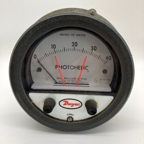
A3040 Dwyer Photohelic Pressure Switch/Gauge (0-40"w.c.)
$485.00
Bezel and front cover with set point knobs and zero adjustment screw
In stock: 1 available
1
A3040 Dwyer Photohelic Pressure Switch/Gauge (0-40"w.c.)
Product Details
Brand: Dwyer
Weight: 5.00 lbs
Applications
- Air conditioner systems
- Clean rooms
- Fume exhaust systems
Features
- Bezel and front cover (with set point knobs and zero adjustment screw) removed to expose Photohelic® switch/gage set point mechanism (cover is clear polycarbonate plastic)
- Gauge pointer and light shutter are mounted on helix and balancing counterweight
- Shutter passes through slot in optical limit switch to expose phototransistors to integral infrared light source or mask them depending on applied pressure
- Light shield effectively protects phototransistors from strong outside light sources yet allows free pointer movement; it also gives interior a clean "finished" look
- Optical limit switches are used for reliability and long service life. Attached directly to set pointers, they are individually aligned to assure precise switching accuracy
- Semi-flexible drive shaft connects to set point knobs
- Zero adjustment screw connects to screw in cover to adjust zero pressure reading
- Plastic enclosure protects electronic components and electrical connections
- Polycarbonate connection or terminal board is self-extinguishing
- Glass epoxy printed circuit boards for durability and permanence
- Load relays are DPDT with latching feature for maximum application versatility
- Electronics are designed to operate on 50/60 Hz, 120 volt current with 10% over or under voltage
- Switch set pointers show switch settings at all times
- Spring loaded friction clutch prevents operator damage of set point mechanism
- 3-in-1 instrument allows the reduction of several instruments with one product
- Unique design and 1% full scale dead band provides quick response to pressure changes means no delay in switching and chatter-free operation
Display prices in:USD

